The workflow editor & node menu
The workflow editor is the part of GiraffeTools you’ll probably spend most of your time building your pipeline. In this window, you’ll initialize the nodes of your pipeline and draw connections between them. In the basics section of this documentation, we’ll explain how to build Nipype-based pipelines in GiraffeTools such as the simple skull stripping pipeline below.
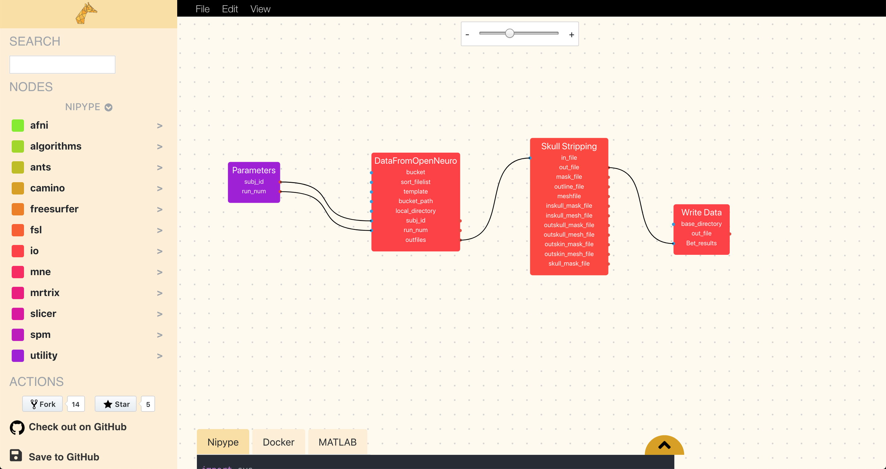
You can have at a look at the pipeline here or check out the code in the GitHub repository. The code for this example can be found in the first-nodes branch.
Nodes in GiraffeTools
When you open GiraffeTools, you’ll start with an empty workflow editor. To begin building your pipeline, you’ll have to drag in some nodes. A “node” represents a specific operation within your pipeline, ranging from neuroscience-specific operations like skullstripping or motion-correction to more generic operations like file I/O.
Currently, GiraffeTools provides nodes based on interfaces from Nipype, a Python-based software package providing wrappers for all major neuroimaging software packages.
Initializing nodes with the node menu
To start building pipelines, you’ll of course need some nodes!
To initialize nodes, navigate through the node menu
on the left of GiraffeTools’s GUI, which shows you all the Nipype-interfaces
that GiraffeTools supports. Selecting, for example, fsl and, in turn, preprocess
shows you all the available nodes from FSL’s preprocessing suite (including the skull
stripping node from the image above, fsl.BET).
Simply drag your node of choice into the workflow editor and reposition as you please!
Input-ports and output-ports
Looking at, for example, the fsl.BET node, you see the name of the interface
(here “fsl.BET”) at the top of the node. Below the name of the interface, the
node’s “ports” (as we call them) are listed. Each port is either an input-port,
recognizable by the little blue dot on the left side of the node, or an
output-port, recognizable by the little red dot on the right side of the node.
In the screenshot of the FSL BET node below, for example, the in_file parameter
represents an input-port, while the out_file, mask_file, outline_file, etc.,
represent the node’s output-ports. (For Nipype-nodes, these input-ports correspond
to the inputs attribute/traits of nodes, and the output-ports correspond to the
outputs attribute/traits.)
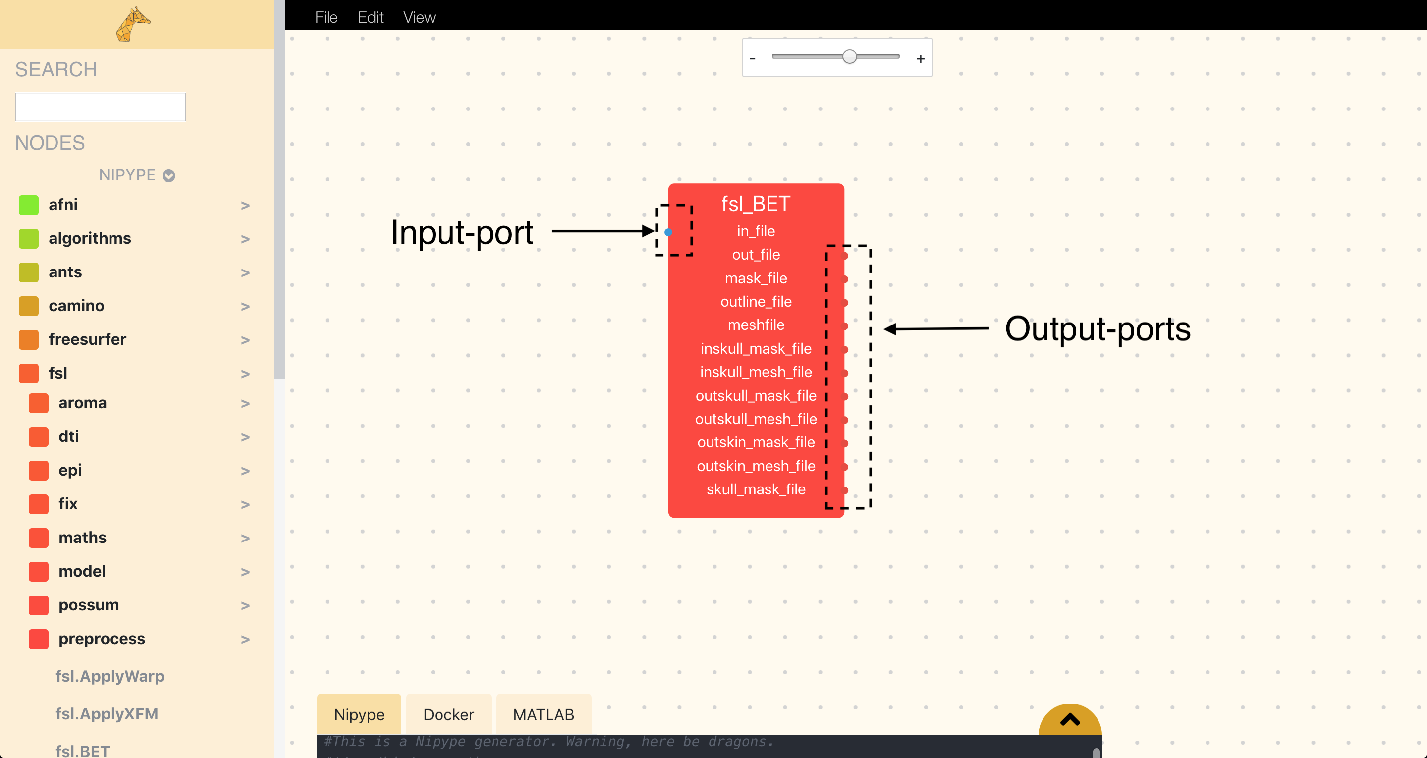
Importantly, by default, the node only shows the mandatory input-ports, while it shows by default all output-ports. In the next section on the parameter editor, you’ll learn how to customise nodes by changing the name (e.g. fsl.BET to Skullstripping), accessing the node’s non-mandatory input-ports and how to control which output ports are shown and which are not (for example, to reduce the visual clutter in pipelines with nodes which have a lot of output-ports.).
Connecting nodes
Now, suppose you’ve created a skull stripping node (fsl.BET) and a node to perform ‘linear image regisration’ (fsl.flirt), it’s trivially easy to connect them.
Just click on an output-port and drag your cursor towards another node’s
input-port, which draws a line between the two ports. To use the results of our
skull stripping, we could for example connect the out_file output-port
from the BET-node (representing the skullstripped structural file) with the
in_file input-port from the fsl.flirt node (representing the file to be used for image registration).
Now, there’s more to building pipelines than initializing and connecting nodes. In the next section on the parameter editor, you’ll learn how to control the functionality and visualization of your ports in more detail!